
Thermal imaging identifies electrical hotspots, insulator failures, and overloaded circuits before catastrophic failure occurs. An infrared camera sees the heat signature of a failing component long before it shows any visible symptoms — enabling planned maintenance instead of emergency repairs.

UAV-based thermal inspection has transformed the economics of power infrastructure maintenance. A single drone flight with an LWIR imager can survey kilometers of transmission lines in an hour — work that would take a crew days on the ground. Automatic anomaly detection algorithms flag thermal outliers for engineer review, dramatically reducing analysis time.
Typical Deployments
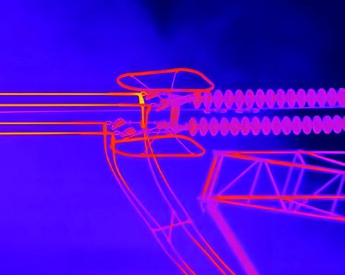
- High-voltage transmission: inspection drones with 1280-class radiometric cores cover long line sections at altitude, resolving hotspots on individual insulators and connectors
- Solar farm inspection: thermal imaging reveals panel defects — bypass diode failures, cracked cells, soiling; a 1 MW farm surveyed in under an hour
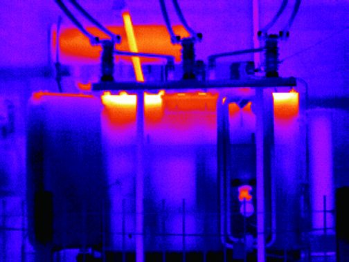
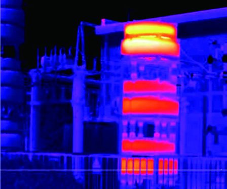
- Substation & switchgear: fixed-mount or portable LWIR systems monitoring transformer oil temperatures, busbar connections, and fuse condition
- Building energy audit: wall-surface thermal mapping revealing insulation gaps, air leaks, and moisture intrusion
What the Camera Sees: Typical Monitoring Points
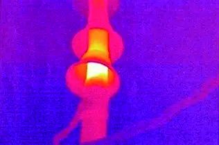
Fixed and UAV-mounted radiometric cameras turn every critical component into a trended measurement zone. The gallery below shows the most common monitoring points across generation, transmission, and distribution assets.
Module Selection Guide
| Scenario | Module | Key figures |
|---|---|---|
| Long-standoff line & insulator survey | SPECTRA L12T (1280×1024) | Radiometric −20–150 / 50–600 °C, <26 g |
| General UAV inspection | SPECTRA L06A (640×512) | ≤300 g with 25 mm lens, price-performance balance |
| Composite insulator assessment | SPECTRA PL06A | Polarimetric material discrimination |
Where drones or other low-altitude targets are part of the threat model, the EO/IR layer can be combined with radar for wide-area detection, track cueing, and image-based confirmation. See Energy Facility Protection for the complementary radar application.