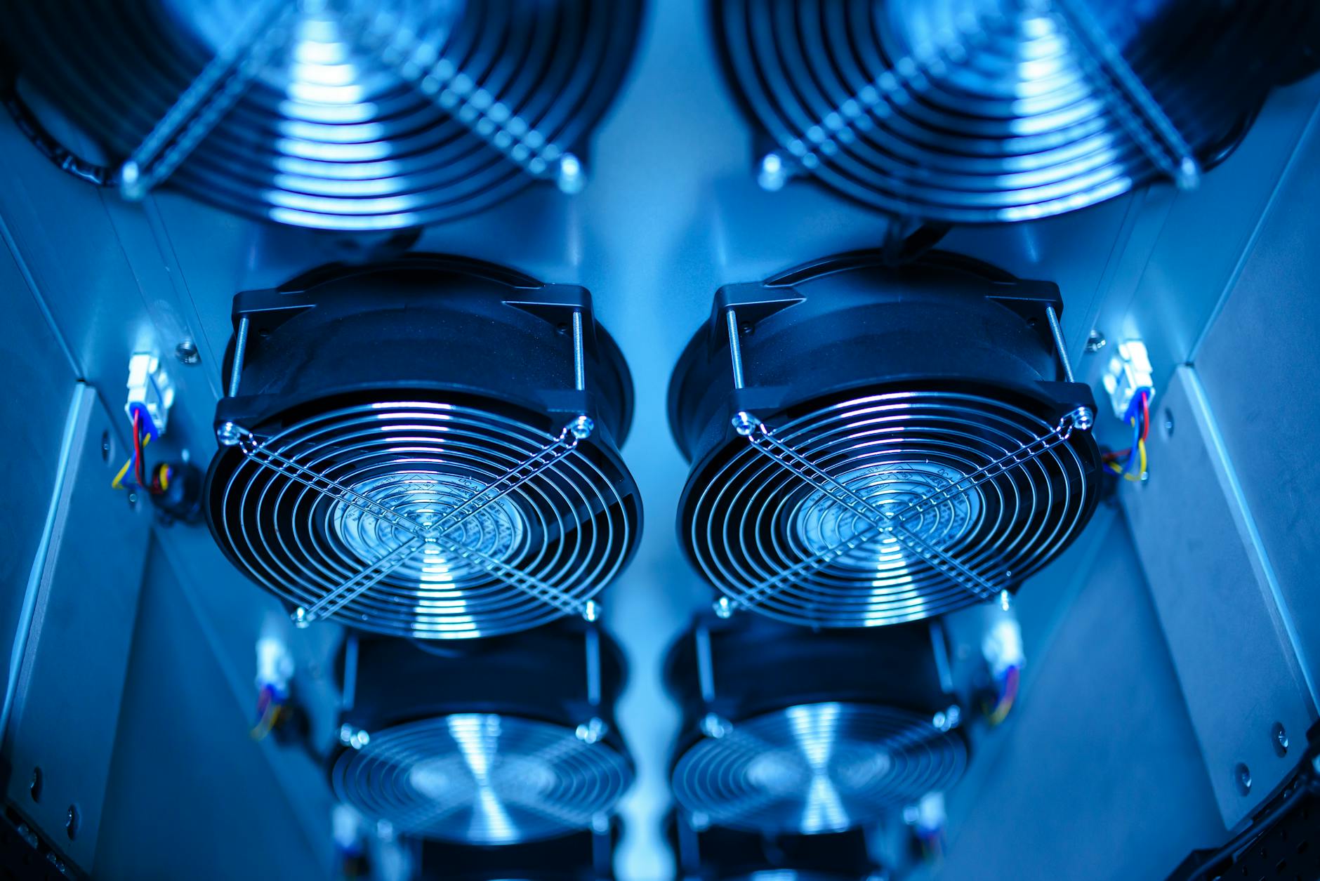
Power consumption in thermal camera cores is not a single detector specification; it is the sum of sensor biasing, readout electronics, image processing, interface circuitry, calibration mechanisms, and, for cooled infrared modules, the active cooling system. For OEM engineers, the practical question is how the core behaves across startup, stabilization, normal imaging, high-frame-rate operation, and environmental extremes, because those conditions determine battery sizing, heat sinking, enclosure design, and system uptime.
What Drives Power Consumption in Thermal Camera Cores?
A thermal camera core converts infrared radiation into digital image data, but several subsystems consume power before a usable video stream is available. In an uncooled LWIR core, the detector array, ROIC, analog front end, ADCs, timing electronics, FPGA or ISP, memory, and output interface are the main contributors. Mechanical shutter actuation, if used for non-uniformity correction, adds short transient demand rather than continuous load.
For cooled MWIR and some high-performance SWIR configurations, the cooling subsystem can dominate the power budget. A Stirling cooler, linear cooler, or TEC does not draw a fixed amount of power under all conditions. It draws more during cooldown, at high ambient temperature, and when heat leakage through the dewar or package increases. Once the detector reaches its operating temperature, steady-state cooler power typically falls, but it still varies with environment and setpoint.
Datasheet power values should therefore be read with their test conditions. Supply voltage, ambient temperature, output mode, frame rate, image-processing state, and time since startup all matter. A module specified at 25 °C ambient and one video output enabled may draw more current in a sealed vehicle enclosure, an airborne pod exposed to solar load, or a multi-stream embedded vision system. Standards such as EMVA 1288 are useful context for camera characterization discipline, even though thermal-core power testing often also requires application-specific operating profiles.
Uncooled LWIR vs Cooled MWIR: Which Uses More Power?
Uncooled LWIR cores generally consume less power than cooled MWIR cores because they do not require cryogenic cooling. Their microbolometer arrays operate near ambient temperature, with power mainly used by detector bias, readout, correction, processing, and interfaces. This makes uncooled LWIR suitable for compact OEM systems where heat dissipation, battery life, or always-on operation is important. A module such as SPECTRA L06A 640×512 LWIR 12μm is typically evaluated in this kind of integration context, where stable operation and low system thermal load are as important as image format.
Cooled MWIR cores provide different imaging performance characteristics, especially where sensitivity, long-range detection, narrow spectral filtering, or high-temperature target contrast is required. The trade-off is higher and more variable power consumption due to the cooler. The cooldown phase must be included in the system budget because it can create a peak load that exceeds steady-state demand. OEMs also need to consider whether the mission profile allows the cooler to remain active, cycle between standby and imaging, or shut down between events.
A cooled module such as SPECTRA M06A 640×512 Cooled MWIR 15μm should therefore be assessed with a time-based power profile rather than a single wattage number. Startup power, time to image, steady imaging power, and recovery from standby can affect the power architecture. In mobile or airborne platforms, these values influence not only battery capacity but also connector rating, DC-DC converter selection, and thermal rejection paths.
The spectral band itself also affects optical and system design. ISO 20473 provides a formal division of optical radiation into spectral bands for optics and photonics, which is relevant when comparing SWIR, MWIR, and LWIR architectures; see ISO 20473:2007. In practice, spectral selection is driven by target physics and atmosphere first, and power consumption is one of the integration constraints that follows.
How Do Frame Rate, Resolution, and Interfaces Affect Power Draw?
Resolution and frame rate influence power because they set the data rate through the detector readout chain and digital processing pipeline. A higher pixel count requires more readout activity, more correction data, more memory bandwidth, and more output bandwidth. A higher frame rate increases the same loads per unit time. The relationship is not always perfectly linear because some subsystems have fixed overhead, while others scale with pixel throughput.
Image correction also matters. Bad-pixel replacement, non-uniformity correction, temporal filtering, local contrast enhancement, electronic stabilization, fusion, tracking, and metadata generation all add processing load. In many OEM products, the thermal core is not the only imaging device. A dual-band module such as FUSION LV0625A 640×512+2560×1440 MIPI 35mm also brings visible-channel capture, synchronization, and fusion processing into the system-level power budget.
Interfaces can be a hidden contributor. MIPI CSI-2 is often efficient for short embedded connections, while Ethernet, SDI, USB, Camera Link, or other high-speed outputs may increase PHY and serializer power. Networked systems may also need compression or packetization, which shifts power from the sensor core into the processor or interface board. ONVIF profiles, described by ONVIF, are relevant to network interoperability, but the electrical cost of producing compliant streams depends on the encoder, SoC, and transport architecture.
For OEM selection, it is useful to define the minimum acceptable operating mode before comparing modules. A 640×512 core at a moderate frame rate may fit a passive observation system, while a high-resolution core or multi-band system may be required for detection, recognition, or AI processing. The correct comparison is not lowest watts alone; it is watts per required imaging function under the operating modes the product will actually use.
How Does Thermal Design Change Power Consumption?
Every watt consumed by the core becomes heat inside the host system, except for small amounts carried away through emitted radiation or external signal energy. If that heat is not conducted out of the camera assembly, internal temperature rises. Higher internal temperature can increase detector noise, alter calibration stability, reduce electronics lifetime, and, for cooled detectors, increase cooler load. Poor thermal design can therefore increase power consumption indirectly by forcing the cooler or correction pipeline to work harder.
The mechanical interface should be treated as part of the electrical design. Mounting surfaces, thermal pads, heat spreaders, enclosure material, airflow, solar loading, and neighboring electronics all affect equilibrium temperature. In sealed products, internal air has limited heat capacity and limited convection; conduction to the housing often dominates. In high-altitude or low-pressure environments, external convection may be reduced, which changes the allowable dissipation path.
Thermal gradients are also important. A core can remain within its maximum operating temperature while still experiencing local hot spots near regulators, FPGAs, or interface PHYs. Those gradients may cause image drift or require more frequent calibration. When an infrared optical assembly is involved, lens temperature can also affect focus and radiometric consistency. ISO 11382 addresses characterization topics for infrared optical materials from 0.78 µm to 25 µm; see ISO 11382:2022 for relevant material-data context.
A practical OEM test should log input voltage, current, housing temperature, core temperature telemetry if available, frame rate, output mode, and image-processing settings. The test should cover cold start, hot start, steady operation, maximum ambient, minimum ambient, and any standby or sleep transitions. Measuring only bench-top steady-state current can miss the conditions that determine field reliability.
When to Use Low-Power Thermal Camera Cores in OEM Systems
Low-power thermal camera cores are most valuable when the product has limited energy storage, restricted heat rejection, continuous operating requirements, or dense electronics packaging. UAV payloads, handheld devices, unattended sensors, mobile robots, and vehicle-mounted perception systems often fall into this category. In Airborne/UAV systems, lower core power can translate into smaller payload power converters, reduced thermal mass, and less impact on flight endurance.
Low power should not be selected in isolation. A lower-power core that requires additional external processing, a larger lens, more frequent calibration, or higher integration complexity may not reduce total system power. Conversely, a core with slightly higher module power but integrated correction, stable output timing, and a suitable interface may reduce power elsewhere in the host platform. OEMs should compare complete imaging chains, including lens heaters, processors, storage, networking, and display or encoder loads.
AI-enabled and multi-band systems add another layer. A product such as NEXUS LV0619B AI multi-band Ethernet/SDI may be selected because onboard processing reduces the need to transmit raw streams to an external computer. In that case, module-level power may increase, while system-level power, latency, or cabling complexity may improve. The right metric is mission energy per detection, inspection, or decision event, not only watts at the module connector.
In vehicle and fixed-site systems, available power may be less constrained, but thermal management still matters. A core that dissipates several additional watts can raise internal enclosure temperature, affect adjacent electronics, and require larger housings or active cooling. For OEM products produced at scale, those mechanical consequences can be more significant than the module power difference itself.
FAQ
What is the typical power consumption of a thermal camera core?
Typical power depends on detector type, resolution, frame rate, interface, processing load, and operating temperature. Uncooled LWIR cores are usually lower power because they do not require cryogenic cooling. Cooled MWIR cores generally draw more power, especially during cooldown, because the cooler is part of the imaging system.
Why does a cooled thermal camera core use more power at startup?
At startup, the cooler must pull the detector down to its required operating temperature. This creates a higher load than steady-state imaging after the detector has stabilized. The startup peak should be included when sizing power converters, batteries, fuses, and connectors.
Does reducing frame rate lower thermal camera power consumption?
Reducing frame rate can lower power in subsystems that scale with pixel throughput, such as readout, digital processing, memory, and output interfaces. The reduction may be limited by fixed loads such as regulators, control electronics, standby processing, or cooler operation.
How should OEMs measure thermal camera core power consumption?
OEMs should measure voltage and current over time in each operating mode: cold start, cooldown, steady imaging, high-frame-rate operation, standby, calibration, and maximum ambient temperature. The measurement should use the final interface, cable length, processing configuration, and enclosure thermal design whenever possible.
What power specification matters most when selecting an OEM thermal module?
The most useful specification is the time-based power profile under the target mission conditions. Peak startup power, steady-state power, standby power, ambient-temperature dependence, and heat dissipation path all affect OEM selection. The best module is the one that meets imaging requirements while fitting the product’s electrical, thermal, and mechanical limits.