How Does Infrared Module Power Consumption Affect System Design?
Infrared module power consumption is not an isolated specification. It changes the power budget, thermal design, enclosure size, battery runtime, startup behavior, and platform payload at the same time. For OEM integration, it is not enough to compare only resolution, NETD, frame rate, and spectral band. If power is underestimated early in the project, the final product may suffer from image drift, overheated housings, insufficient battery life, excessive UAV payload, unstable startup, or reduced long-term reliability.
For procurement teams and system engineers, power consumption should be treated as a design boundary rather than a small line item in a datasheet. The difference between a 3 W uncooled LWIR module and a 20 W cooled MWIR module is not just 17 W. It may require a different battery pack, cable gauge, DC-DC converter, heat path, gimbal design, environmental test plan, and acceptance criterion.
How Much Power Does an Infrared Module Consume?
Uncooled LWIR modules usually have relatively low power consumption. For a 640×512, 12μm-class uncooled long-wave infrared module, typical steady-state operating power is often in the range of about 1.5–3.5 W, although startup transients may be higher than the stable value. Modules such as the SPECTRA L06A 640×512 LWIR 12μm are well suited for handheld instruments, UAV payloads, mobile robots, perimeter sensors, and low-power edge perception systems.
A 1280×1024-class uncooled LWIR module normally consumes more power because of the larger readout circuit, higher data throughput, more processing, and faster interface requirements. In many system-level designs, this class may fall into the 4–8 W range. The higher resolution can provide a wider field of view at useful detail, or better target recognition at the same field of view, but the power supply, thermal path, image processing chain, and data interface must all be sized accordingly.
Cooled MWIR modules consume significantly more power. A 640×512, 15μm-class cooled mid-wave infrared module may require around 10–20 W after the detector reaches stable cooling, including the detector, cooler, and processing board. During cooldown, peak power may reach 1.5–2 times the steady-state level. A module such as the SPECTRA M06A 640×512 Cooled MWIR 15μm is appropriate for long-range detection, high sensitivity, and day/night operation in complex backgrounds, but the system must reserve enough margin for cooler startup.
High-temperature cooled MWIR, high-resolution cooled arrays, dual-band payloads, and AI imaging systems may push power demand even higher. This is why module selection should start with an honest operating scenario: ambient temperature, duty cycle, frame rate, output format, image processing load, startup conditions, and platform power availability.
How Does Infrared Module Power Consumption Affect Power-Supply Design?
Power-supply design should begin with three current values: startup peak current, steady-state average current, and maximum current under extreme environmental conditions. For example, a cooled infrared module rated at 12 V and 15 W draws about 1.25 A during stable operation. If the startup peak is estimated at 30 W, instantaneous current may reach 2.5 A. If the power module is sized only for the steady-state value, it may trigger undervoltage protection during low-temperature startup, battery sag, or long-cable operation.
For vehicle, UAV, and robotic platforms, a practical rule is to reserve at least 30% power margin. For cooled infrared modules, dual-band payloads, and multispectral systems, 50% margin is often more realistic. If the system also includes a visible-light camera, laser rangefinder, gimbal motors, AI compute board, wireless transmission unit, heater, defogger, or storage device, the infrared channel should not be budgeted in isolation. A complete platform-level power table is required.
In Airborne/UAV applications, a 10 W difference in payload power may translate into several minutes of flight endurance. It can also affect battery discharge rate, connector selection, wire diameter, voltage drop, and gimbal balance. On 24 V or 48 V platforms, engineers often use local DC-DC conversion near the imaging payload. Converter efficiency must be included. If a DC-DC converter is 88% efficient, a 20 W infrared load actually draws about 22.7 W from the main bus.
Startup sequencing also matters. If the infrared cooler, visible camera, AI board, wireless transmitter, and gimbal controller all start at the same time, the combined inrush current may exceed the power rail limit. A staged startup design can reduce peak load and improve system reliability. Procurement specifications should therefore ask vendors for typical power, maximum power, startup current, allowed voltage range, warm-up or cooldown time, and recommended power sequencing.
How Does Infrared Module Power Consumption Change Thermal Design and Housing Size?
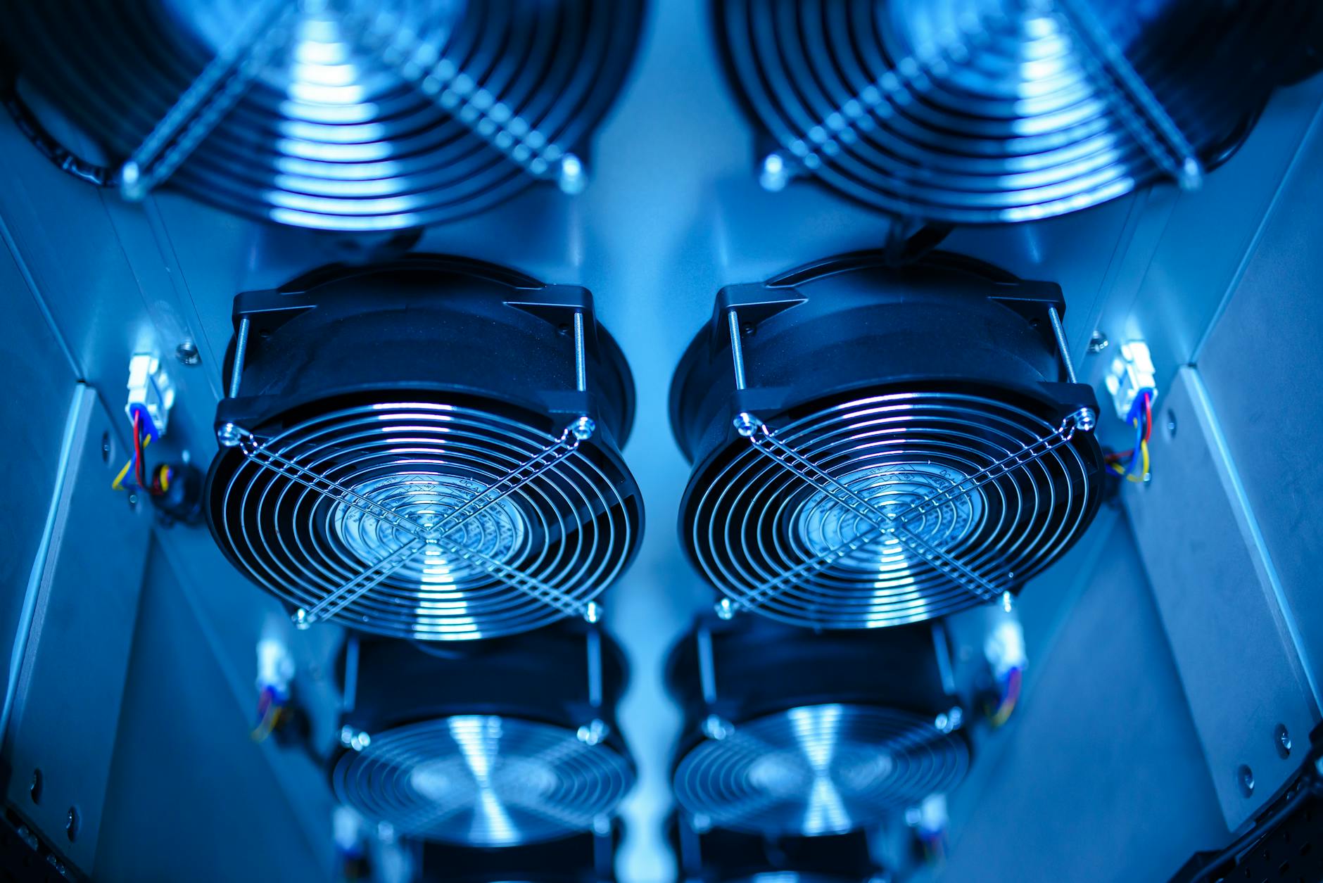
Most of the electrical power consumed by an infrared module eventually becomes heat. A 3 W uncooled module in a compact sealed cavity already needs a defined thermal conduction path. A 15–30 W cooled module must transfer heat deliberately to the enclosure, heat sink, cold plate, or forced-air cooling structure. If heat accumulates near the detector, lens mount, processing board, or calibration mechanism, the result may be thermal drift, higher noise, more frequent non-uniformity correction, longer stabilization time, and reduced image consistency.
A simple thermal-resistance calculation is useful in early design. If an infrared module releases 8 W into the enclosure and the total thermal resistance from internal mounting point to ambient air is 5°C/W, the internal temperature rise is about 40°C. In a 45°C ambient environment, local internal temperature may approach 85°C. That level can shorten the life of electronic components and reduce system margin during solar loading, sealed operation, or continuous high-frame-rate use.
Cooled MWIR modules require special attention to hot-side heat rejection. If the cooler’s hot side cannot dissipate heat efficiently, cooler power increases, cooldown time becomes longer, and the image may take more time to stabilize. This can be a serious issue for surveillance systems that must start quickly, for UAV payloads that run in thin airflow, and for compact electro-optical pods where the heat path is constrained by size and weight.
Thermal design should also consider where the heat goes. Dumping heat into the optical bench may shift focus. Dumping heat into the lens area may increase local gradients and affect image uniformity. Dumping heat into the sealed electronics cavity may increase board temperature and reduce processor reliability. The best approach is to create a short, low-resistance path from the module’s thermal interface to a structural heat sink or enclosure surface, then verify the design with temperature sensors and thermal imaging during prototype tests.
For general engineering references, teams may consult the ISO standards catalog for environmental and reliability frameworks, ONVIF for network video interoperability considerations, and EMVA for machine-vision interface standards such as GenICam. These references do not replace a module vendor’s thermal recommendations, but they help structure system-level requirements and test documentation.
Infrared Module Power Consumption vs Battery Life, Interfaces, and AI Compute
Power consumption also pulls on data links, processing architecture, and compute selection. A 1280×1024 infrared module outputting at high frame rate produces far more data than a 640×512 module. The downstream ISP, video encoder, AI inference board, storage module, and transmission link may all consume more power as a result. In other words, increasing detector resolution may increase not only sensor power but also the power of every stage after the detector.
Dual-band systems add another layer. The visible-light sensor, synchronization controller, fusion processor, and interface board must all be included in the system budget. A visible channel may look inexpensive in isolation, but when paired with real-time fusion and transmission, the total load can be meaningfully higher. This is why dual-band design should be evaluated as “infrared + visible + fusion algorithm + interface + mechanical cooling,” not as a detector-only decision.
When single-board AI is introduced, inference power must also be counted. Lightweight object detection may add 2–5 W. A higher-performance AI platform may add more than 10 W. Systems such as the NEXUS LV0619B AI multi-band Ethernet/SDI integrate sensing, processing, and output functions, so the design team should evaluate the complete imaging workload rather than only the infrared detector.
For mobile robots, this affects much more than battery life. Additional heat can change cabin temperature, sensor placement, enclosure ventilation, and long-term reliability. For vehicle-mounted systems, extra power may be acceptable, but heat rejection, vibration robustness, and cable routing become more important. For fixed surveillance systems, power is less constrained, but enclosure temperature, solar loading, and maintenance intervals are still critical.
Battery-runtime calculations should use realistic duty cycles. A handheld device that runs the infrared module continuously but enables AI only on demand will have a different runtime from a robot that performs continuous detection, recording, and wireless streaming. Engineers should build at least three operating profiles: standby, normal imaging, and maximum load. Procurement teams should require suppliers to define the power conditions behind any quoted runtime.
When to Use Low-Power LWIR, Cooled MWIR, Dual-Band, or AI Imaging
The best selection process starts with a power boundary before choosing the highest-specification module. Handheld devices, small UAVs, compact robots, and battery-operated sensors usually benefit from uncooled LWIR modules. In these systems, a target module-level power range of 3–8 W is often more manageable, especially when the product also includes display, recording, communication, and embedded processing.
Long-range surveillance, border monitoring, maritime observation, and high-temperature target detection may justify cooled MWIR. The tradeoff is clear: higher sensitivity and range performance in exchange for a larger power budget, startup peak, cooldown time, and more demanding heat rejection. For these applications, the system should reserve space and power for a 10–30 W infrared load, plus startup margin and thermal hardware.
High-resolution, dual-band, and AI-fusion systems should be calculated as complete imaging subsystems. The correct budget includes the infrared module, visible sensor, processing board, AI accelerator, encoder, interface board, storage, heaters, motors, and cooling structure. Looking only at detector power can lead to undersized batteries, unstable startup, unexpected enclosure temperatures, and delayed field deployment.
During the prototype stage, teams should record at least five values: startup peak power, steady-state power, power at maximum ambient temperature, image stabilization time, and enclosure temperature rise. These values should be measured in realistic operating modes, not only on an open bench at room temperature. For sealed products, tests should include the final enclosure, lens, gimbal, cable harness, and expected mounting orientation.
A procurement specification should ask the supplier for typical power, maximum power, startup current, operating temperature range, thermal mounting conditions, cooldown or warm-up time, and interface power requirements. For cooled modules, the specification should also identify cooler startup behavior and hot-side heat dissipation needs. For AI systems, it should define the inference mode, frame rate, model load, and output format used during power measurement.
FAQ
Q1: Is an uncooled infrared module always better for low-power systems?
Usually, yes. Uncooled LWIR modules commonly fall around 1.5–8 W, while cooled MWIR modules are often 10–30 W or higher. However, if the application requires long-range small-target detection, a cooled module may be the right choice despite higher power consumption.
Q2: Can I use typical power consumption from the datasheet for power-supply design?
Not by itself. The power supply should be designed around maximum power and startup peak current, with margin for low temperature, battery voltage drop, DC-DC efficiency, cable voltage loss, and simultaneous startup of other subsystems.
Q3: Does higher infrared module power consumption directly reduce image quality?
Power consumption is not an image-quality metric, but poor heat dissipation can cause thermal drift, higher noise, more frequent correction, longer stabilization time, and lower image consistency. The indirect impact can be significant.
Q4: What power loads are most often missed during infrared module integration?
Commonly missed items include cooler startup peak power, AI compute boards, video encoding, gimbal motors, wireless transmission, heating and defogging elements, storage devices, and DC-DC conversion loss.
Q5: How should I compare infrared module power consumption for UAV payloads?
Compare total payload power, not only detector power. Include the infrared module, visible camera, gimbal, AI processor, encoder, transmitter, voltage conversion loss, and thermal hardware. Then translate the total into battery draw and expected flight-time impact.