A rear-window defroster is a printed resistor: silver heating lines fired onto the glass, connected by bus bars at both edges. If a line is scratched through during handling, printing, or edging, that strip of the window simply never defrosts. The defect is invisible to the eye — the break can be a hairline — but obvious to a thermal camera the moment current flows.
This case covers an automotive glass processor that moved defroster inspection from sampling to 100% inline testing, using a camera built around an OEM thermal core.
Project Background
In late 2023, an automotive glass processor in East China supplying rear windows to three domestic EV brands was dealing with a warranty problem: defroster failures were surfacing at dealerships months after delivery. The plant runs two tempering lines producing roughly 4,000 rear lites a day, and defroster continuity had always been checked by sampling — a few pieces per shift on a bench multimeter. In January 2024, the quality team piloted a 100% inline thermal inspection station at the exit of Line 1.
Pain Points of the Traditional Approach
The plant’s original quality check was electrical: measure the total resistance of the grid and reject panels outside tolerance. It caught catastrophic failures — a severed bus bar, an open circuit — but not a single broken line. One open strip changes total resistance only slightly, well inside the pass window, and still leaves a permanent blind band across the driver’s rear view.
Visual inspection had the opposite problem: operators could find scratches, but only under carefully angled light, at line speed that didn’t scale, and with no record of what passed.
The Thermal Imaging Solution
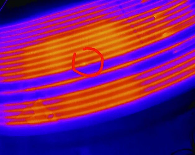
The redesigned station is simple in concept. After edging, each panel is indexed into a fixture and the defroster grid is energized for a few seconds at a controlled voltage. A thermal camera looking at the full panel captures the grid as it warms:
- Intact lines heat evenly and show up as continuous bright traces.
- A broken line heats only up to the break — the far side stays dark, making the gap unmissable.
- Shorts and local thinning appear as hot spots where current density is abnormally high.
The camera is built around a radiometric LWIR core, and the inspection software compares the measured line pattern against the expected template, then marks any discontinuity and diverts the panel. Every panel gets tested, and every result is stored with its thermal image for traceability.
What the Thermal Solution Changed
- Escape rate to near zero. Single-line breaks that passed resistance testing are now caught at 100% inline coverage.
- Objective, archived evidence. Every panel ships with a stored thermal image — useful both for customer claims and for tracking print-process drift back to the silk-screen line.
- No added tact time. The energize-and-image cycle fits inside the existing indexing time of the line.
Module Selection Notes
Inline inspection stations like this need a radiometric core with stable output over long production runs, a frame rate fast enough to freeze the heating transient, and an interface that drops straight into machine-vision software. The SPECTRA L06A 640×512 LWIR core is the usual starting point; smaller stations with tight budgets can step down to the 384×288 L04 series. For more industrial integration patterns, see the industrial inspection application page.
Building an inline thermal inspection station? Contact our engineers to discuss core, lens, and interface selection for your line speed and working distance.