A powered circuit board is a thermal map of its own health. A shorted capacitor, a cracked solder joint under load, an over-clocked regulator — each announces itself as a hot spot long before it becomes a burnt smell and a dead board. The trick is seeing millimeter-scale components with enough thermal resolution to name the culprit, and the question is whether that stays a lab technique or becomes a production one.
This case looks at how an electronics contract manufacturer built thermal failure analysis in its lab — and then moved it onto the line.
Project Background
In 2024, the quality department of an EMS plant in the Pearl River Delta — twelve SMT lines building industrial control boards — counted the cost of its failure-analysis bottleneck. Boards failing functional test went to a small FA lab where engineers hunted faults with a multimeter, a bench supply with current limiting, and freeze spray: inject power, watch the current, spray, watch for the frost line to shift, repeat. A tricky short took an engineer most of a day; the lab’s backlog ran two weeks; and a growing share of returns from the field were intermittent faults that passed bench retesting. Meanwhile, escaped early-life failures were showing up at customers as dead-on-arrival boards. The department funded a thermal FA workstation — a near-focus radiometric thermal camera on a stand over the bench — and, after the first quarter’s results, a second system mounted inline as a powered screening step for the highest-value product family.
Pain Points of the Traditional Approach
- Hunting a short by feel is slow. Freeze-spray and current-sensing work, but they localize a fault to a region, not a component — and each iteration costs an engineer minutes of setup and minutes of waiting.
- Intermittent faults escape. A marginal joint that fails under thermal load looks perfect on a cold bench; the lab’s “no trouble found” rate was rising in step with field returns.
- The backlog distorts priorities. A two-week FA queue meant process engineers saw defect data long after the lot that made it — corrective action lagged the process drift that caused the failures.
- Test coverage ends at power-off. Functional test proves a board works at that moment; it says nothing about the components running abnormally hot that will fail in month three.
The Thermal Imaging Solution
The lab workstation images the powered board with a radiometric 640×512 LWIR core fitted with a close-focus lens — spatial resolution fine enough to separate adjacent 0402 passives. The workflow becomes visual: power the board, watch the thermal video, and the faulty component lights up. A shorted capacitor is a bright point in the first seconds; a resistive joint warms steadily under load; a stressed regulator runs its own signature temperature.
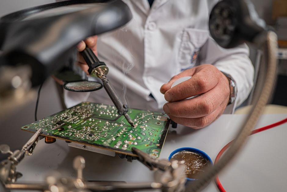
For the intermittent cases, the lab added a second view: a SWIR camera imaging through the board’s own materials to check for subsurface defects in packages, while thermal cycling on the bench reproduced the field failure live on the thermal feed. On the line, the inline station powers each board for a fixed soak and compares its thermal image against a golden-board template — any component outside its temperature envelope fails the station before the board ships.
What the Thermal Solution Changed
- Diagnosis time fell from hours to minutes. The lab’s median time-to-localize dropped from most of a day to under an hour; the two-week backlog cleared in the first month and has not returned.
- “No trouble found” cases fell sharply. Thermal cycling under the camera reproduced most intermittent field failures on the bench, converting dead-end returns into identified root causes.
- Process feedback went same-day. FA findings now reach the line while the affected lot is still traceable; two reflow profile drifts were corrected in-day that would previously have run for a week.
- Early-life failures got screened out. The inline thermal station catches abnormal components before shipping; dead-on-arrival returns on the screened product family fell by more than half in two quarters.
Module Selection Notes
PCBA thermal work needs a radiometric LWIR core with close-focus optics for component-level spatial resolution and stable measurement at small spot sizes. The SPECTRA L06A 640×512 LWIR core with a macro lens is the lab and inline standard; the SPECTRA S06A SWIR module adds see-through-material inspection for packaged devices. See the industrial inspection application page for electronics inspection patterns.
Setting up a failure-analysis bench or an inline thermal screening station? Talk to our engineers about core selection, close-focus optics, and station integration.