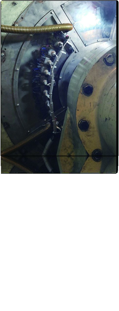
Carbon brushes are consumable parts, but they fail expensively. In a hydro generator, the brush gear and slip rings carry excitation current into the rotor; when a brush wears unevenly, sticks in its holder, or loses spring pressure, contact resistance rises and the contact point heats up. Left alone, that heat damages the slip ring surface — and a scored slip ring means pulling the unit offline for machining, not swapping a ten-dollar brush.
This case looks at how a large hydropower station moved from manual rounds to continuous thermal monitoring of the brush gear, using a fixed camera built around an OEM thermal core.
Project Background
In March 2024, a large hydropower station in Central China — four 250 MW Francis units on a tributary of the Yangtze — began a retrofit of its generator auxiliary monitoring. The plant’s twelve electricians cover eight generator floors of rotating equipment, and brush-gear inspection had always been a manual, once-per-shift walk with a handheld pyrometer. After a scored slip ring on Unit 2 forced a five-day unplanned outage the previous autumn, the station approved a fixed thermal monitoring pilot covering the brush gear of all four units.
Pain Points of the Traditional Approach
The station’s maintenance routine was typical: an electrician walked the generator floor with a handheld pyrometer once per shift, noted brush and slip-ring temperatures in a logbook, and flagged anything unusual.
Three gaps kept showing up:
- A snapshot, not a trend. Brush temperature under load changes with excitation current and ambient conditions. A once-per-shift reading easily misses a brush that runs hot only under high load.
- Access is awkward and risky. The brush gear sits inside a rotating machine. Getting a good emissivity-corrected spot reading on a small carbon block next to a spinning slip ring is neither safe nor repeatable.
- No alarm path. If a brush started overheating at 2 AM, the first signal was often the next morning’s reading — or the smell of burning insulation.
The Thermal Imaging Solution
The integrator mounted a fixed thermal camera with a clear view of the brush ring and excitation cabinet, built around a 640×512 uncooled LWIR core with temperature measurement output. The camera streams radiometric data to the plant’s monitoring system, where each brush region is defined as a measurement zone with its own alarm threshold.
Because the core outputs temperature per pixel rather than just a video image, the back-end software can trend every zone independently and raise an alarm when a single brush runs, say, 15 °C above its neighbors — the classic signature of a sticking brush or weak spring.
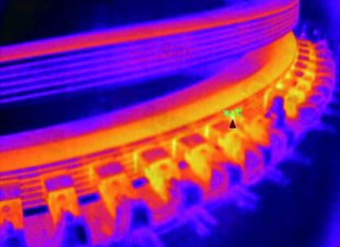
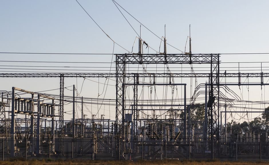
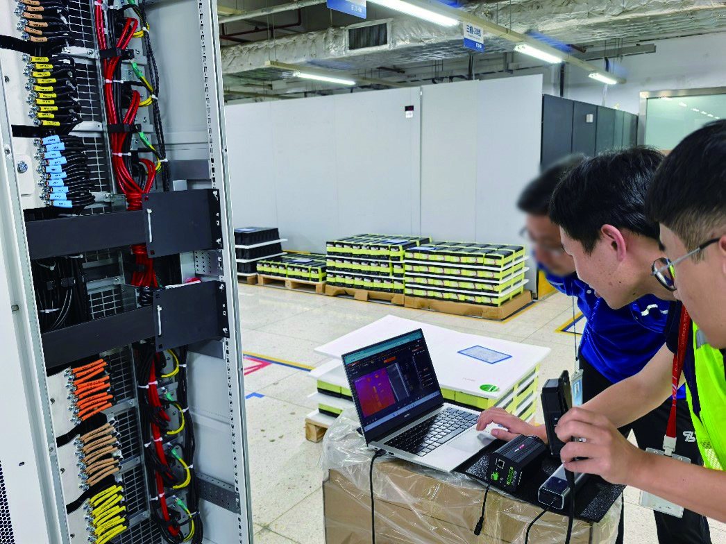
The same monitoring architecture extends naturally to the rest of the powerhouse. The excitation cabinet, station busbars, and transformer bushings are all standard measurement targets for fixed LWIR cameras:
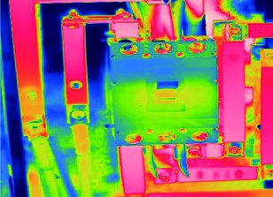
What the Thermal Solution Changed
- From periodic to continuous. Every brush is now measured many times per minute, under every load condition — the data needed for real trend analysis.
- Earlier, cheaper interventions. Brushes are replaced on condition instead of on schedule or after failure, and slip-ring damage has been avoided since the system went in.
- A safer routine. Electricians no longer lean into rotating equipment with a spot thermometer; they review thermal trends from the control room.
Module Selection Notes
For this class of fixed monitoring, the requirement is a radiometric LWIR core with stable temperature output, a lens matched to the working distance, and an interface the back-end software can poll continuously. The SPECTRA L06A 640×512 LWIR core covers the mainstream case; where the camera must also cover a wide powerhouse view in detail, the 1280×1024 SPECTRA L12NT gives the extra pixels. See the power inspection application page for related deployment patterns.
Planning a fixed monitoring project for rotating machinery or electrical rooms? Talk to our engineers about core selection, optics, and interface options.