Every mechanical test is a conversation with a specimen, and strain gauges hear only the syllables spoken exactly where they are glued. Thermography hears the whole specimen at once. Under cyclic load, a material’s temperature follows its stress field — the thermoelastic effect — and where damage begins, hysteresis heating lights the spot before a crack has a length worth naming. For a fatigue lab, a sensitive thermal camera is not a camera at all: it is a full-field stress instrument and an early-warning detector sharing one sensor, asking nothing of the specimen but a matte coat of paint.
This case looks at how a university fatigue laboratory integrated thermal imaging into its test frames — and what full-field thermal eyes did to composite qualification work.
Project Background
In 2024, the structural testing laboratory of a university in central China — a dozen servo-hydraulic frames running fatigue and static programs for aerospace and rail suppliers — took stock of two recurring costs. The first was instrumentation labor: complex composite coupons arrived with requests for strain maps, and wiring forty gauges per specimen consumed days of technician time while still leaving the space between gauges unmeasured. The second was late crack detection: on long fatigue runs, failure initiation was found by scheduled stops for dye-penetrant or ultrasonic checks — each stop unloading the specimen and disturbing the very damage state being studied. The lab approved a thermography capability: high-sensitivity radiometric cameras dedicated to the busiest frames, with lock-in analysis software for thermoelastic stress mapping and continuous heating monitors for fatigue runs.
Pain Points of the Traditional Approach
- Point sensors can’t map a field. Strain gauges measure where they are bonded; stress concentrations between gauges are inferred, not seen — and on composites the interesting stress fields change within millimetres.
- Full-field optical methods have their own tax. Digital image correlation gives full-field strain but demands lighting control, speckle preparation and line of sight — and says nothing directly about the heat that damage generates.
- Scheduled inspections disturb the test. Stopping a million-cycle run every fifty thousand cycles for NDT unloads the specimen, restarts transient heating, and still only samples the damage at the stops.
- Cracks announce themselves late. By the time dye penetrant finds a surface crack, the damage has a history nobody recorded — the initiation moment, and the weeks of precursor heating before it, are lost.
The Thermal Imaging Solution
The lab deployed two thermographic techniques on the busy frames. For stress mapping, specimens under cyclic load are imaged with a high-sensitivity radiometric camera while lock-in software extracts the tiny temperature oscillation that tracks the load — the thermoelastic signal, a few millikelvin deep. The result is a full-field stress map of the specimen surface: not points, but a picture in which stress concentrations at holes, ply drops and bond lines appear directly, calibrated against a handful of reference gauges instead of a forest of them.
For fatigue monitoring, the same cameras simply watch, continuously, at ordinary frame rates. Damage announces itself as local hysteresis heating: a warm spot that appears at a ply interface, grows, and migrates — recorded with its full history, without touching the test. Technicians now stop runs when the thermal record says damage has initiated, not when the calendar says to look; initiation life — the number that actually feeds fatigue models — is read from the heat trace rather than back-calculated from a found crack.
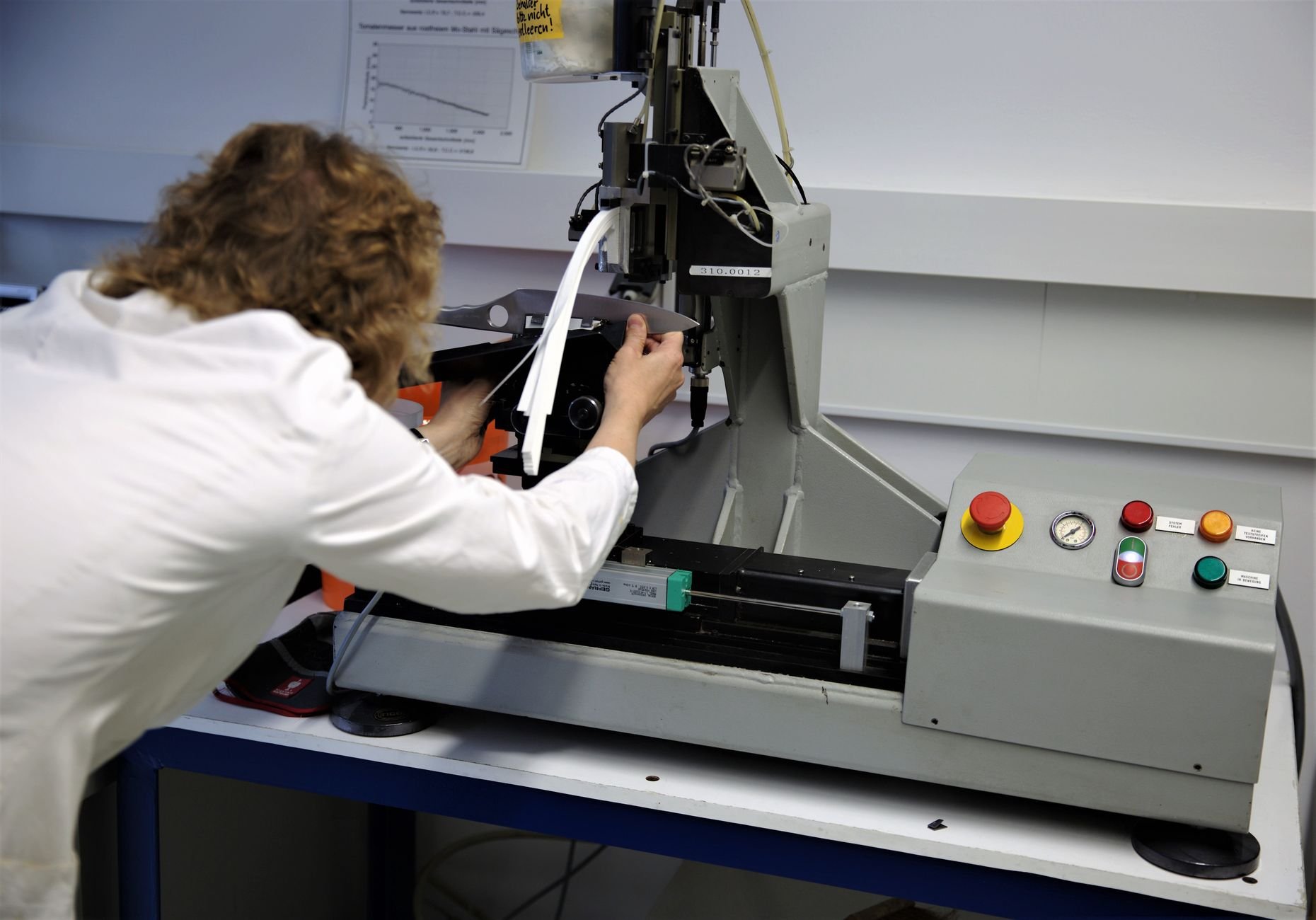
The qualification programs felt the difference immediately. Composite coupon matrices that had been sized around gauge-labor limits were re-planned around thermal full-field coverage, and the lab’s customers began requesting the thermal stress maps as deliverables in their own right.
What the Thermal Solution Changed
- Gauge counts fell, coverage rose. Reference-instrumented thermoelastic mapping replaced dense gauge arrays on routine coupons — technician hours per specimen dropped sharply while measured coverage went from points to the full field.
- Crack initiation is now an observation, not an inference. Thermal precursor monitoring logs the moment and location damage starts; the lab reports initiation life directly instead of bracketing it between inspection stops.
- Unscheduled failures stopped ambushing programs. Continuous heating monitors flag accelerating damage early enough for planned stops — specimens reach their targets, and the destructive surprise ending has become rare.
- The lab sells a new deliverable. Full-field stress maps and damage-evolution thermal records are now line items in customer programs — capability the lab previously subcontracted or declined.
Module Selection Notes
Thermoelastic work is a sensitivity contest: the signal is millikelvins riding on ambient temperature, so the camera’s NETD is the entire instrument, and stable radiometry over hours-long runs matters more than resolution. The SPECTRA L06A 640×512 LWIR module is the laboratory workhorse for fatigue monitoring and general thermography. Where the program demands the deepest thermoelastic sensitivity or high-speed capture of transient events, the SPECTRA H10A cooled MWIR module is the research-grade step up. See the scientific research application page for laboratory imaging patterns.
Equipping a test lab or a materials research program? Talk to our engineers about sensitivity requirements, lock-in workflows and camera integration.