Why Industrial Equipment Inspection Depends on Infrared Thermography
Infrared thermography for industrial equipment inspection is not mainly about “seeing more clearly.” Its real value is converting temperature abnormalities in electrical connections, bearings, furnaces, pipelines, insulation layers, and drive components into data that can be recorded, compared, and traced without shutdown, contact, or disassembly. For continuous production lines, finding an overheated terminal block or a poorly lubricated pump bearing early is often far more valuable than replacing a failed motor and troubleshooting after the line has stopped.
What Faults Can Infrared Thermography Find in Industrial Equipment?
Most industrial faults show thermal signatures before full failure. Loose terminals inside electrical cabinets, three-phase load imbalance, aging contactors, and degraded cable joints often appear as localized temperature rise. Bearing wear or insufficient lubrication in motors, fans, pumps, and gearboxes may create stable hot spots around bearing housings, end covers, or couplings. Steam pipelines, damaged insulation, and leaking valves can produce abnormal temperature bands distributed along the pipe route.
In practical inspections, relative temperature difference is often used for first-level risk assessment. A 5–10°C difference between similar components should usually be recorded and rechecked. A difference above 20°C often justifies scheduling a maintenance window. For motor insulation systems, engineers also need to compare readings against insulation class limits, such as Class B at 130°C, Class F at 155°C, and Class H at 180°C. Image color alone is not enough; the value of infrared images is that they preserve the image, temperature points, timestamp, and operating condition as evidence.
Relevant inspection methods can be cross-checked against ISO 18434-1:2008, which covers condition monitoring and diagnostics using thermography. For plants building internal inspection competency, personnel qualification guidance is also available in ISO 18436-7:2014.
How Does Infrared Thermography Work for Industrial Equipment Inspection?
Infrared thermal imaging detects radiation emitted from object surfaces and converts it into temperature distribution data. In plant inspection, this allows technicians to compare live equipment under load without touching energized cabinets, opening high-risk covers, or stopping production. The inspection target may be a busbar joint, cable lug, motor bearing, steam trap, furnace wall, valve body, gearbox housing, or conveyor drive.
The key is not a single absolute temperature reading. A reliable inspection compares temperature against operating load, ambient temperature, emissivity, reflected temperature, distance, and similar components under similar duty. For example, a motor end cover at 70°C may be normal in one process but abnormal in another. A cable connector only 15°C warmer than ambient may still be high risk if adjacent phases under the same current are much cooler.
This is why mature programs build thermal baselines. Each critical asset should have an initial thermal image captured under normal load. Later inspections can then compare monthly, weekly, or shift-level changes. Over time, the plant can distinguish seasonal variation from true deterioration.
Industrial Equipment Infrared Thermography Specifications Buyers Should Check
When purchasing infrared equipment, “temperature measurement” is only the starting point. For inspection-grade use, engineers and procurement teams should evaluate at least four parameters: resolution, thermal sensitivity, measurement range, and optical field of view.
A 640×512 detector is suitable for most electrical cabinets, pump rooms, production line assets, and robot-based inspections. If the target is farther away or physically small, such as elevated busbars, dense pipe racks, or large plant areas, a 1280×1024-class module provides more pixels on target and better detail retention. Thermal sensitivity, usually specified as NETD, should generally be ≤50 mK for industrial inspection. Lower NETD makes it easier to distinguish small temperature differences in early bearing abnormalities, minor insulation defects, or weak heat leakage.
For uncooled long-wave infrared applications, the SPECTRA L06A 640×512 LWIR 12μm is a practical fit for fixed online monitoring, handheld inspection devices, and mobile robots. Where larger image coverage and longer-distance detail are required, the SPECTRA L12NT 1280×1024 LWIR is better suited to high-value equipment zones and wide-area inspection routes.
Optics matter as much as detector format. A wide lens is useful in compact electrical rooms, while a narrow field of view is better for distant cable joints, high-mounted valves, and furnace observation points. Procurement teams should request sample images or field trials at the actual inspection distance, because nominal resolution alone does not guarantee enough pixels on the fault target.
When to Use Infrared Thermography for Electrical, Furnace, and Pipe Rack Inspection
The best priority areas for infrared thermography usually share three characteristics: high failure cost, high risk for manual access, and a strong relationship between temperature change and failure mode.
The first category is electrical equipment: switchgear, transformers, bus ducts, cable joints, distribution boxes, and motor control cabinets. Overheating often comes from increased contact resistance, poor crimping, loose bolts, oxidation, or load imbalance. Infrared inspection can complete first-level screening without de-energizing equipment. A more systematic deployment approach is described under Power Inspection.
The second category is high-temperature assets, including kilns, heating furnaces, boilers, heat-treatment lines, and casting production lines. Standard LWIR may work for many surface inspections, but extreme temperature or strong radiation backgrounds may require wider dynamic range, filtering, and cooled MWIR technology. For furnace lining defects, molten material zones, and high-temperature process window monitoring, the SPECTRA H10A 1024×768 HT-Cooled MWIR is a better technical match.
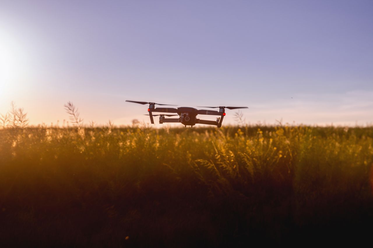
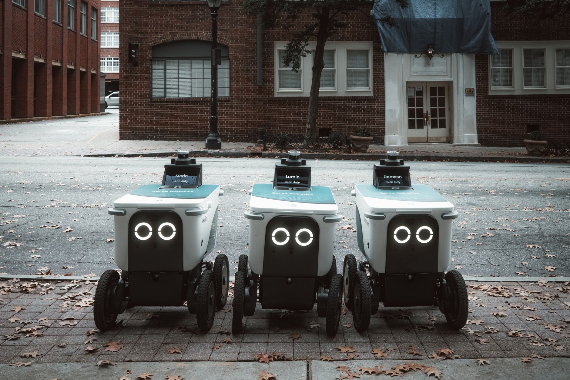
The third category is unmanned or semi-automated inspection. When thermal imaging is combined with visible imaging, AI recognition, and planned inspection routes, factories can reduce manual meter reading and missed inspections. This is especially useful in substations, chemical plants, long pipe corridors, warehouses, and large manufacturing sites where the same route must be repeated under consistent conditions.
Infrared Thermography vs Vibration Analysis: Which Is Better?
Infrared thermography and vibration analysis solve different parts of the reliability problem. Thermography is stronger for overheating, friction, insulation loss, electrical contact issues, furnace wall anomalies, and thermal leakage. Vibration analysis is stronger for imbalance, misalignment, looseness, bearing frequency defects, resonance, and rotating machinery diagnostics.
For example, an early bearing defect may first appear in vibration spectrum data before a large surface temperature change is visible. But once lubrication deteriorates or friction increases, the bearing housing may develop a stable hot spot that is easy to capture in a thermal image. Similarly, a loose electrical terminal may not create any vibration signature, but it can create a clear localized temperature rise under load.
For critical motors, fans, pumps, compressors, and gearboxes, the better answer is usually a combined program. Use vibration to diagnose mechanical signatures and infrared thermography to verify heat generation, lubrication condition, and electrical health. The two datasets help maintenance teams avoid both missed faults and false alarms.
How to Choose an Infrared Camera or Module for Industrial Inspection
A practical selection process should work backward from four variables: inspection distance, target size, temperature range, and installation method.
For close-range electrical cabinets, pump rooms, bearing checks, and routine walkaround inspection, 640×512 LWIR is usually sufficient. For small targets at longer distance or dense equipment zones, 1280×1024 should be prioritized. For high-temperature furnaces, metal heat processing, and strong radiation backgrounds, cooled MWIR should be evaluated. For robots, UAVs, or fixed online monitoring, confirm interface and integration requirements such as MIPI, GigE, USB, synchronization trigger, SDK support, edge computing interfaces, and enclosure constraints.
Measurement range is another key decision. A camera optimized for building inspection may saturate when pointed at a furnace wall or high-temperature process. Conversely, a high-temperature configuration may not provide the best sensitivity for low-temperature bearing or insulation defects. Plants with mixed assets may need multiple configurations rather than one universal camera.
Deployment should also include workflow design. Reports should preserve ambient temperature, load rate, emissivity setting, inspection distance, abnormal point temperature, and visible-light context where possible. Without these records, later comparisons become subjective and difficult to audit.
A clear starting recommendation is to begin with three asset groups: power distribution systems, key rotating equipment, and thermal pipe networks. Use 640×512 LWIR to build a repeatable inspection loop first. If the plant already has robots, drones, or an online monitoring platform, then upgrade selected routes to higher-resolution, dual-band, cooled, or AI-enabled systems based on actual fault detection requirements.
FAQ
Q1: Can infrared thermography replace vibration testing for industrial equipment?
No. Infrared thermography is better for overheating, friction, insulation defects, and electrical abnormalities. Vibration testing is better for imbalance, looseness, misalignment, and bearing frequency faults. Critical rotating equipment should normally use both.
Q2: What affects infrared temperature accuracy during equipment inspection?
The main factors are emissivity, reflected temperature, distance, lens focal length, viewing angle, ambient conditions, and obstruction. Shiny metal surfaces reflect surrounding heat and can create large reading errors, so inspectors often use comparison points or high-emissivity tape for verification.
Q3: Is 640×512 resolution enough for industrial infrared inspection?
For most near- and mid-range inspections, yes. If the target is very small, far away, or mounted high above the floor, a 1280×1024 module or a narrower field-of-view lens may be needed to capture enough detail.
Q4: Should a factory choose fixed online monitoring or handheld inspection?
Fixed online monitoring is better for high-risk, continuously operating assets where shutdown cost is high. Handheld, robot, or route-based inspection is better when assets are numerous, risks are distributed, and periodic checks are acceptable. Both methods can use the same abnormality criteria and reporting templates.