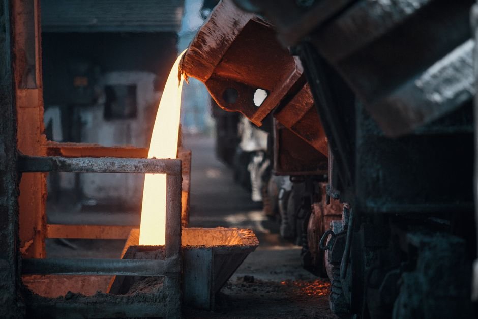
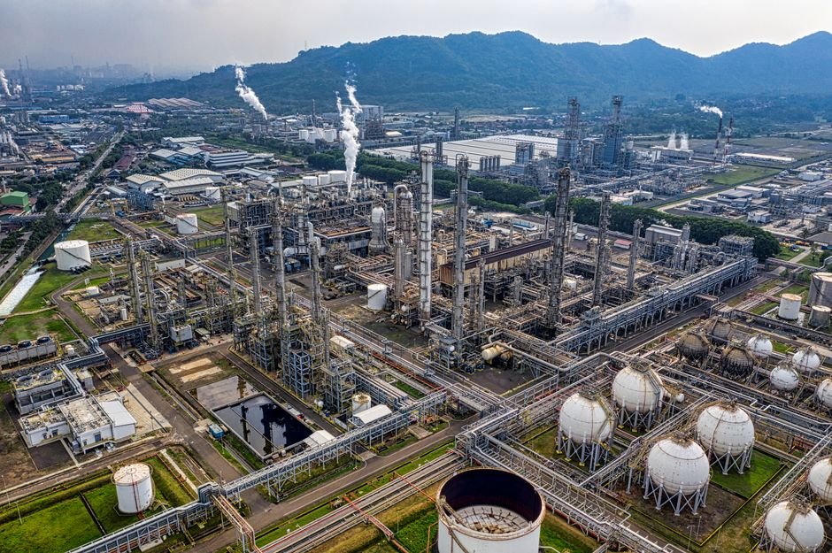
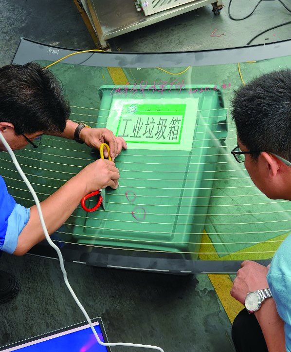
A glass furnace is one of the hottest, most valuable and least observable machines in industry. Inside, fifteen hundred degrees of molten glass is held in a refractory box for years of continuous campaign; the melt’s temperature distribution governs product quality, and the refractory’s condition governs whether the campaign ends on schedule or catastrophically. The plant knows the furnace’s health through a few thermocouples and the outgoing glass — a bit like flying an airliner by watching the wake. The reason is physical: at these temperatures, in these atmospheres, most sensors simply cannot look inside. The ones that can are cooled mid-wave infrared cameras, chosen for the wavelengths that see through furnace atmospheres to the glass itself.
This case study looks at how a float glass plant instrumented its furnace and float bath with cooled MWIR imaging, and what seeing the melt changed.
Project Background
In 2023, the process engineering team of a float glass plant in north China — a single large furnace feeding a float line producing architectural and automotive glass around the clock — reviewed two persistent blind spots. First, melt temperature: the furnace’s few thermocouples measured points, drifted over months, and died young in the atmosphere; the actual temperature distribution across the melt — the thing that sets homogeneity and defect rates — was inferred from product defects rather than measured. Second, refractory condition: the furnace walls wear for the whole campaign, and the wear pattern decides the rebuild schedule; the plant’s evidence was external shell-temperature surveys by handheld camera, done monthly, from whatever access the structure allowed. The team approved a cooled MWIR imaging project: cameras viewing the melt through existing furnace peepholes, plus fixed thermal monitoring of the critical refractory zones from outside.
Pain Points of the Traditional Approach
- Thermocouples were few, drifting and mortal. A handful of point sensors in a hall-sized furnace, each with a limited life in the atmosphere, could never describe the melt’s temperature field — and their slow drift poisoned what data they did give.
- Defects were the real sensor. Cord, stones and other melt-quality defects announced temperature-distribution problems — after the bad glass was already made and sold or scrapped.
- Refractory wear was estimated from the calendar. Campaign planning leaned on experience and monthly shell surveys; hot spots developing between surveys had room to grow unseen.
- Uncooled cameras could not see the melt. LWIR imagers measure the furnace atmosphere and peephole radiation more than the glass; at these temperatures and geometries, the physics demands a cooled MWIR sensor.
The Thermal Imaging Solution
The project installed cooled MWIR cameras at engineered viewing positions. Through the furnace peepholes, the cameras image the melt surface directly: mid-wave infrared at these temperatures sees the glass through the combustion atmosphere well enough to map temperature across the melt, giving the process team a continuous field instead of a few drifting points. The melt maps expose cold and hot zones, feed-back into combustion tuning, and — trended over weeks — describe the furnace’s condition with a resolution the thermocouples never approached.
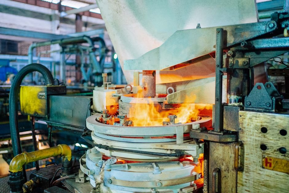
On the float line, cameras watch the glass ribbon and the tin-bath region, where the forming temperature profile decides optical quality; and on the furnace exterior, fixed thermal monitoring of the critical refractory zones replaced the monthly walk-round, trending shell temperatures continuously and alarming on developing hot spots.
What the Thermal Solution Changed
- Melt temperature became a field, not a guess. Combustion is now tuned against the actual melt map; the process team reports measurably tighter temperature distribution and a corresponding reduction in melt-related defects.
- Refractory wear moved from calendar to condition. Continuous shell trending revealed a developing hot zone at one wall area mid-campaign — early enough to add cooling and adjust the rebuild plan in an orderly way rather than as an emergency.
- The forming process stabilized. With the ribbon’s thermal profile visible continuously, tin-bath adjustments are made against data; optical-quality first-pass yield improved and its day-to-day variance narrowed.
- Thermocouple dependence dropped. The remaining contact sensors are now validated against the cameras rather than the reverse; sensor drift is caught instead of absorbed.
Module Selection Notes
Furnace and melt imaging is the classic duty for a cooled MWIR core: high sensitivity, the spectral band that penetrates furnace atmospheres at high target temperatures, and the stability to trend over a years-long campaign. The SPECTRA H10A cooled MWIR module is built for high-temperature process imaging of exactly this kind; for the exterior refractory and balance-of-plant duty, an uncooled radiometric core such as the SPECTRA L12T 1280×1024 LWIR module covers shell monitoring economically. See the process monitoring application page for furnace and high-temperature patterns.
Instrumenting a furnace, kiln or high-temperature process? Talk to our engineers about cooled MWIR selection, viewing geometry and campaign-length trending.